Answers to those Doggone Thermal Design Questions
By Tony Kordyban
Copyright by Tony Kordyban 2003
Dear Thermal Guru,
In your column last August you wrote about the possibility of a fan that could stir up the air in an enclosure by flapping back and forth like a traditional Japanese fan. What you thought was a joke is already being developed as real technology. I found so-called “Miniature and Ultrasonic Piezoelectric Fans” developed by a research group at Purdue University. (http://docs.lib.purdue.edu/cgi/viewcontent.cgi?article=1056&context=coolingpubs)
Your Biggest Fan in Littleton
Dear Big,
That is why my wife doesn’t read my writing anymore. She complains that I can’t make up silly ideas for technology faster than real researchers. I once tried to make fun of component package manufacturers by pretending they released a Ball Grid Array (BGA) that had solder balls on the top of the package as well as the bottom. Two weeks later somebody sent me a copy of the patent for the BGA with solder balls on both sides. It did not explain how anybody could make the electrical connections to both sides, but the technology had been developed.
So I am not surprised to find out that the “push-pull” or flapping fan already exists. Check out the Purdue University web site link above. There are a couple of interesting video clips showing the tiny fan in operation. The work is a couple of years old by now.
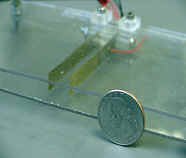 The idea is pretty simple. You attach a plastic strip, or flapper, to a piezoelectric element. The element (or elements, as in this picture with double flaps), when electrical power is applied, vibrates and wiggles one end of the strip. If you wiggle it at its resonant frequency, you get a large movement, and it pushes air away at the free end.
Purdue did not invent this. Their innovation is in making the assembly small enough that it could be used to cool individual chips inside a cell phone or Personal Digital Assistant (PDA). The research is continuing, although I could not find any commercial products that have made use of it yet.
I suppose that such a fan could be useful. Obviously there isn’t room for a rotary fan inside a cell phone housing. A wiggling blade might be able to sweep away the air around a high power chip, to keep a pocket of stagnant, high temperature air from building up. The purpose of such a fan is not ventilation, but to stir the air around.
The people who made the video clip for Purdue don’t seem to understand the problem though. They showed a woman holding a cell phone to her ear, complaining that the phone was too hot to hold comfortably against her face. The narrator follows with the claim that the new miniature fan, developed by Purdue scientists, just might solve this problem.
Not exactly. It won’t help unless the woman is complaining about one small hot spot on the surface of the phone.
An internal fan can equalize the difference between hots spots and cold spots, but it can’t make the phone housing cooler overall. The only way to make the housing cooler is to force air to flow through vents in the phone, and I don’t think they want to add vents. They go to great lengths to keep outside air (and moisture and dirt) from getting into the housing. Given that the phone is sealed, and the total power is fixed, the average surface temperature is determined by the external heat transfer conditions, not any internal fan. If the whole body of the phone is too hot to touch, adding an internal fan (of any type) won’t help at all.
In my extensive research on this topic (typing “piezoelectric fan” into Google) I have found that the flapper fan has been in use to cool electronics off and on since the early 1970’s. The piezo fan can be traced back in history as far as 700 BC. As you know, “piezo-” is the Greek word for “pizza”, (source: the father in the movie My Big Fat Greek Wedding) and legend has it that such a fan was used to stoke the fires of the first wood-fired pizza ovens. In more modern times, a piezoelectric fan was offered as an add-on “silent” fan for one version of the Apple Macintosh in the 1980’s.
 If this discussion gives you an itch to try a piezoelectric fan in your box, there is at least one vendor that offers them as standard, off-the-shelf parts, with spec sheets and everything. They are not miniature, like the ones from Purdue. Piezo Systems, Inc. (www.piezo.com) sells the one shown here. The flapper is about 3 inches long by 0.5 inches wide, and swings back and forth about an inch. (For my metric-minded friends, the dimensions in millimeters are also shown.) For 30 mW of power you can get 2 CFM (0.9 l/sec) of air flow, or so the data sheet claims.
I am not advising anybody to use this or not use it. It looks like it would be fun to play with, to see what it could do, how rugged it is, what is sounds like when mounted to a circuit board.
In my own personal view, this kind of fan is not going to be a big player in the electronics field. For the price and space it consumes, it doesn’t deliver much air flow, compared to a rotary fan. And the fact that it runs at resonance bothers the mechanical engineer hidden deep inside me. I was always taught to design structures to avoid resonance in vibration. Resonance is what super villains in comics use to knock down bridges and buildings with just a pocket-size oscillator. So I can’t help but wonder how long the flaps can flap until they snap.
I can think of one reason to use a piezoelectric flapper. Let’s say you have a box with some hard-to-get-rid-of hot spots. You monkeyed around with the component placement and you juggled the positions of the vents as much as possible. No dice, so you tried a small rotary fan to stir the air around, as a last resort, and it works. But the top brass in your company hate fans. They think of fans a those noisy things that fail. You are forbidden to add fans, no matter how cheap, quiet, redundant or reliable you can make them.
Instead of a fan add a PEAAD (PiezoElectric Atmosphere Acceleration Device). Or an ETG (Electronic Turbulence Generator). It doesn’t look like a fan. It doesn’t spin or have bearings or grease. It might not even have the word “fan” in its material description (if you write the component spec properly). Would that help you slip it past management into your design?
—————————————————————————————————————
Dear Mr. Anti-Theta JC,
Not long ago you wrote an article that said we shouldn’t use Theta j-c (the thermal resistance from junction to case) to calculate junction temperature. You claimed that it might give an estimate of the junction temperature that was lower than the actual junction temperature.
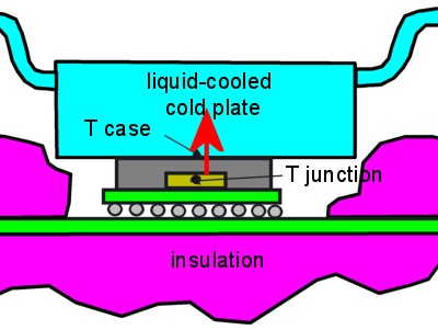
One justification you gave was that Theta j-c was measured in a stirred liquid bath, which has a convection coefficient many times greater than in the typical air cooled application. For your information, the latest test method for Theta j-c, and the one most commonly used, is the Top Cold Plate Method. In this test the bottom of the printed circuit board is insulated and a liquid-cooled cold plate is clamped against the top of the component, forcing nearly all of the heat from the die through the top of the package.
Doesn’t that version of Theta-jc give you a safe estimate of junction temperature?
Luke the JEDEC Knight
Dear Luke,
Amazing! I didn’t know there was yet another completely different way to measure Theta j-c. I guess that’s because there is no JEDEC standard yet for how to measure it.
 Assuming that the cold plate method really does force nearly all the heat from the die to pass through the top of the package where case temperature is measured, then the value of Theta j-c should be a pretty safe way of estimating junction temperature. (For those who don’t remember, a common, but not accurate way of finding junction temperature from case temperature is this equation:
Tjunction = Tcase + Power total x Theta j-c )
In this method, Theta j-c should be about equal to the actual thermal resistance from the junction to the top of the package, which I have called Rj-c in the past. In this method, the value of Theta j-c will not include the effect of having a large circuit board acting as a heat sink. My main problem with Theta j-c is that people assume it is a measure of the resistance between the junction and top of the package. In reality, it is a measure of the resistance between the junction and ambient, mostly through the leads and the printed circuit board to which it is soldered. This cold plate method appears to get rid of that problem.
The cold plate Theta j-c should be especially good for components intended to be used with large heat sinks. (Other ways of measuring Theta j-c are very bad with large heat sinks.)
But I still have a couple of warnings about using Theta j-c to estimate junction temperature:
in a typical application with no heat sink, the junction temperature estimate is likely to be a lot higher than the actual junction temperature. This is “safe”, but not accurate. It might lead you to add a heat sink or fan that you don’t really need.
Because there is no industry standard yet, you don’t know how Theta j-c was measured, unless you ask the component supplier. You can’t just take a value from a web page or a data sheet and assume it was measured using the cold plate method. Theta j-c measured in a wind tunnel or liquid bath test will have a totally different value, and is not necessarily safe.
So unless you know where your Theta j-c came from, continue to use with intense skepticism. You really should go back to my original article (November 2002) to get a better understanding of the problem with Theta j-c. Intense skepticism is how I treat everything anyway, even things like “instant” coffee. It isn’t really instant, is it? It still takes 5 or 10 seconds to dissolve. And even then, is what you get really “coffee”?
—————————————————————————————————————
Isn’t Everything He Knows Wrong, Too?
The straight dope on Tony Kordyban
Tony Kordyban has been an engineer in the field of electronics cooling for different telecom and power supply companies (who can keep track when they change names so frequently?) for the last twenty years. Maybe that doesn’t make him an expert in heat transfer theory, but it has certainly gained him a lot of experience in the ways NOT to cool electronics. He does have some book-learnin’, with a BS in Mechanical Engineering from the University of Detroit (motto:Detroit— no place for wimps) and a Masters in Mechanical Engineering from Stanford (motto: shouldn’t Nobels count more than Rose Bowls?)
 In those twenty years Tony has come to the conclusion that a lot of the common practices of electronics cooling are full of baloney. He has run into so much nonsense in the field that he has found it easier to just assume “everything you know is wrong” (from the comedy album by Firesign Theatre), and to question everything against the basic principles of heat transfer theory.
Tony has been collecting case studies of the wrong way to cool electronics, using them to educate the cooling masses, applying humor as the sugar to help the medicine go down. These have been published recently by the ASME Press in a book called, “Hot Air Rises and Heat Sinks: Everything You Know About Cooling Electronics Is Wrong.” It is available direct from ASME Press at 1-800-843-2763 or at their web site at http://www.asme.org/pubs/asmepress, Order Number 800741.