Answers to those Doggone Thermal Design Questions
By Tony Kordyban
Copyright by Tony Kordyban 2003
Dear Thermal Consultant without Equal (or cost),
 My problem is a little weirder than the ones you normally deal with. I use a special component that not only needs to get rid of a lot of heat in a small space, but its temperature must be 75°C plus or minus 5°C, or it just won’t work. When the ambient is hot, it needs to get rid of lots of heat, but when the ambient is cold, I’d like to reduce the heat loss so it can regulate its own temperature. Why add a secondary heater when it generates lots of heat already?
I know I can’t use a passive solution like a heat sink. I need some kind of temperature controller, maybe a thermo-electric cooler. But that is expensive, eats power, and takes up space I don’t have.
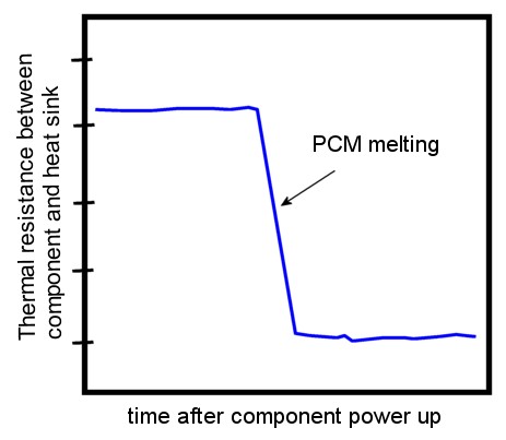
I was looking at this chart from a brochure for a Phase Change Interface Material. It seems to say that when it heats up to a particular temperature, the thermal resistance goes way down. This sounds like just the thing I need. When the temperature goes up, the PCM changes resistance, and lets more heat out to the heat sink. When the temperature is low, the resistance is high, and keeps more heat in the component.
Can this really be the answer to all my prayers?
Sounds too good to be true in Puget Sound
Dear Sounds,
I am glad to find a fellow skeptic. I won’t play the lottery because I know that if I win the big prize I’ll be hit be lightning on the way to collect it.
There might be such a “thermal valve” material out there in the universe someplace. No physical law prevents such a thing from existing. It’s just that the Phase Change Materials used for heat sink interfaces don’t do what you think.
 They do change thermal resistance when they melt, but only once. They don’t change back to high resistance when they solidify again. Let me explain why.
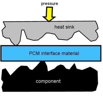
This picture greatly exaggerates the nooks and crannies on the surfaces of the heat sink and the component. It is those mismatches between the two surfaces that create the high thermal resistance in the first place. The solid surfaces would barely touch each other at all.
This is what it looks like when you first put the cold, solid pad of Phase Change Material between the surfaces. It does nothing to improve the thermal resistance, and might even make it worse by adding another layer between them. There are lots of air pockets separating the heat sink from the component. Tiny pockets of air are pretty good thermal insulation.
Don’t ignore that little yellow arrow on top of the heat sink labeled “pressure”. For the Phase Change Material (PCM) to do its magic, the heat sink has to be free to move, and there has to be some downward pressure. The next picture will make that more clear.
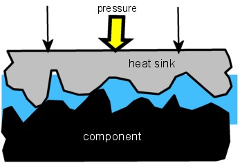 In this picture the component has been powered on for a while. It has heated up above the melting point of the PCM, and the now grease-like material is free to be smooshed. The pressure on the heat sink squishes it down until it makes hard contact with the surface of the component. The PCM wets both surfaces, flowing into many (probably not all) of the tiny crevices and pores, displacing the air from the joint. It is this wetting of the surfaces which lowers the
thermal resistance, not the conductivity of the PCM itself. You might even say that the conductivity was “immaterial”. Ha. Ha.
What happens between the first picture and the second picture is what leads to that sudden drop in resistance in your chart. But what happens when you shut off the power and the component cools below the melting point of the PCM, and the PCM re-solidifies?
I’d show you a picture of that, but I don’t have to because it would look exactly the same as the previous picture. The PCM solidifies, but it doesn’t pop back to its original shape. It stays tucked into all the nooks and crannies, and the heat sink stays in contact with the component. The only difference is that the PCM can’t flow, until it melts again.
What is the thermal resistance with re-solidified PCM? The PCM brochure probably doesn’t say. Most users don’t care what the thermal resistance is when the circuit is turned off. My guess is that the joint thermal resistance is pretty much the same as when it is melted. The contact resistance stays the same. Maybe the conductivity of the grease is slightly different from the solid version, but probably not by much. It’s not as if it changed to a real liquid, just a gooier solid. If the pressure is good, and the surfaces fairly flat, then the thickness of the material in the joint is very small anyway. In my opinion, the change in joint resistance would not be measurable.
To solve your real problem — how to make a joint with reversible thermal resistance, all I can think of is that you could attach your heat sink to a motor. When the component is too hot, press the heat sink down hard. When the component is too cold, reverse the motor and pull the heat sink away. A small air gap should allow your component to heat up again. Use a temperature sensor to control the motion of the heat sink. Maybe the interface material should be a foam rubber pad instead of PCM, so it won’t get pumped out of the joint over time.
Do you think a small stepper motor, some levers and cams, and a controller would cost more than a thermoelectric cooler and its controller? Let me know if my idea works out. I want to be listed on the patent (but not on the lawsuits.)
—————————————————————————————————————
Dear Tony,
I agree with you regarding the need for a large (relative to the electronic box) environmental chamber to simulate ‘still air’, and the use of solar lamps. (See June 2003 article.) One way around this is to use a very large cardboard box, like from a refrigerator, as your environmental chamber. Install the lamps as far above the test unit as possible. Be sure to use enough lamps to get 1,000 W/m*2 at the test unit. Install heaters in the big box. By trial and error keep increasing the heat load (heaters) until you maintain 40 C ambient. Be sure the thermocouple measuring ambient near the test unit is shielded from the lamps above. You may have to vent the box by cutting holes here and there to maintain the 40C condition. A somewhat crude approach, but I think it would simulate the environmental conditions better than one could in an environmental chamber.
Mr. Natural from Sun City
Dear Nat,
I have seen the kind of “home-made” environmental chamber you talk about in various electronics development labs over the years (although I have never seen one equipped with solar load lamps — those are pretty expensive to be tossing into a refrigerator box held together with duct tape.) It is possible that they were just as good at representing a customer’s environment as an official “environmental chamber.” A refrigerator box can be hard to control, leaky, inaccurate, give unreproducible results, and might even be a safety hazard. But it has the undeniable quality of being cheap.
I have amused myself over the years during boring meetings by trying to design a workable environmental chamber that could test electronic equipment under “still air” conditions. I wasn’t even trying to solve the problem of producing a realistic solar load. I was thinking about indoor equipment which is supposed to function in so-called natural convection or still-air.
Everybody has their own idea of what “still air” means. It means that you don’t have fans blowing at your equipment. Enhanced air flow would cool the electronics. But other than the negative definition of “no forced air blowing on the equipment”, how should a “still air” environment be defined? The purpose of such a definition is to come up with a way of testing a product, so that when a customer uses it in a place where the air isn’t blowing around, it still has a pretty good chance of working thermally.
I never did come up with a good way of defining a “still air” environment. One starting point would be a large room that has no heat sources in it, and no ventilation. In such a room after a long time there would be no air currents, and the air would eventually all settle down to the average temperature everywhere. That would be “still air.” Is there such a room in real life, except in an abandoned building?
What happens as soon as you put heat generating electronics into the room? The heat from your box starts a plume of warm air rising for the ceiling. That generates a complex, slow, 3-dimensional circulation pattern throughout the room. The air is no longer still, and no longer all at one temperature. And unless you start removing heat from the room somehow (ventilation, conduction), the average air temperature is going to go up, and keep going up. That heat removal mechanism is going to create flow patterns and temperature gradients of its own.
If you try somehow to stifle these flows and gradients, then you are blocking the very mechanism of natural convection which is supposed to cool your product. That doesn’t seem like a very fair test!
So, given that a “still air” chamber must have some air flow and variation in air temperature from place to place, how much flow and how much temperature gradient can there be and still qualify as a “still air” environment? And if the temperature is not uniform, where do you define the “ambient” temperature?
I never came up with an answer to satisfy myself. At least not a single answer.
I imagine that the “still air” environment is very different for each of these examples:
- a laptop computer sitting on a hotel desk
- a laptop computer on someone’s lap in a center seat of a commercial airliner
- a network server in an unventilated wiring closet
- a rack-mounted box in a large telecom central office surrounded by high power equipment
- a rack-mounted telecom box in an underground vault
- an electronic module under a car hood shortly after shutting off the engine after a long summer drive
I have probably not even listed the “still air” environment that you have to design for. There is probably a different kind of “still air” for every kind of customer. For that reason I am very pessimistic about being able to design a chamber that can adequately represent the “still air” environment for product validation testing.
You see why a refrigerator box isn’t so bad. Even the most expensive environmental chamber isn’t very realistic. With either one you are approximating what you guess is the customer environment. One is just more approximate than the other.
—————————————————————————————————————
Isn’t Everything He Knows Wrong, Too?
The straight dope on Tony Kordyban
Tony Kordyban has been an engineer in the field of electronics cooling for different telecom and power supply companies (who can keep track when they change names so frequently?) for the last twenty years. Maybe that doesn’t make him an expert in heat transfer theory, but it has certainly gained him a lot of experience in the ways NOT to cool electronics. He does have some book-learnin’, with a BS in Mechanical Engineering from the University of Detroit (motto:Detroit— no place for wimps) and a Masters in Mechanical Engineering from Stanford (motto: shouldn’t Nobels count more than Rose Bowls?)
 In those twenty years Tony has come to the conclusion that a lot of the common practices of electronics cooling are full of baloney. He has run into so much nonsense in the field that he has found it easier to just assume “everything you know is wrong” (from the comedy album by Firesign Theatre), and to question everything against the basic principles of heat transfer theory.
Tony has been collecting case studies of the wrong way to cool electronics, using them to educate the cooling masses, applying humor as the sugar to help the medicine go down. These have been published recently by the ASME Press in a book called, “Hot Air Rises and Heat Sinks: Everything You Know About Cooling Electronics Is Wrong.” It is available direct from ASME Press at 1-800-843-2763 or at their web site at http://www.asme.org/pubs/asmepress, Order Number 800741.
Leave a Reply
You must be logged in to post a comment.