Answers to those Doggone Thermal Design Questions
By Tony Kordyban
Copyright by Tony Kordyban 2003
Dear Mr. Doggone Answer Guy,
I have a question for you. We have many circuit board applications for vacuum environments. Often the thermal analysis is performed by doing a board level thermal analysis to get a board temperature at the location of a component, and using a Theta j-c for that component to back out a junction temperature. (Often a Theta j-b value doesn’t seem to be available.)
So, is using Theta j-c conservative in this vacuum analysis? Does it make sense to use a Theta j-c for a board to junction resistance?
We would appreciate any help you could provide.
Penny from Lost in Space
Dear Penny,
This reminds me of the question I answered in my November 2002 column, which asked whether using Theta j-c to estimate junction temperature from case temperature is conservative. If you aren’t familiar with Theta j-c and its pitfalls, I suggest you check out that column. It has lots of basic definitions I’m going to use here.
By conservative, what Penny and I mean is that we don’t expect Theta j-c to give us an accurate estimate of the junction temperature (Tj). But if there is error, we hope that it will be in the safe direction. We want our prediction to be too high, rather than too low. If we make an estimate that is too low, we might bless a design that will end up being too hot and fail unexpectedly. We can easily live with a component that is colder than expected.
My November 2002 column concluded that Theta j-c was NOT guaranteed to give a conservative estimate of Tj. Depending on the construction of the component package and the environmental conditions of your application, it can give Tj either too high or too low.
Penny’s problem is somewhat different from the November 2002 question. She isn’t using the case temperature (Tc) to find the junction temperature — she wants to use the temperature of the printed circuit board (PCB) directly under the component. Somehow she is able to come up with a local board temperature (Tpcb) under a component, and lacking any better information about the component, wants to know if she can safely estimate junction temperature from this equation:
Equation 1 Tj (estimate) = Tpcb + Q x Theta j-c
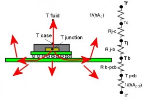
Figure 1. In the JEDEC test measuring Theta j-c, heat flows out of the die through at least two paths. Theta j-c is a composite value of most of these resistances.
where Q is the total power dissipation of the component.
I am already suspicious of this method, because it is using a starting point (Tpcb) that is only distantly related to Theta j-c. It is like deciding how good a movie is going to be by studying its advertising poster. At least some of the information on it is related to the movie itself, but you never know how much. But my gut has been wrong before. It doesn’t trust me (not since that chili dog at the county fair) and I don’t trust it. So I fired up my handy spreadsheet program and did a few calculations to back my gut up.
First let’s draw up a couple of resistor diagrams to compare the heat transfer paths of the Theta j-c JEDEC test method, and Penny’s application of a board in a vacuum.
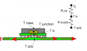
Figure 2. Because of the vacuum, heat can flow only into the board, so there is only one path for it to follow.
The resistor network for Penny’s application is a lot simpler. The component is mounted on a PCB in a vacuum. Heat can’t flow out through the top of the package, because there is no fluid to carry it away. (I am going to ignore radiation from the package for the time being.) All of the heat flows through the bottom of the package into the board, and by conduction to other parts of the board, then perhaps to a cold plate.
These resistor networks are simplifications of the real heat paths for a real component. But in general we can say that heat flows either into the air or into the board. If there is no air, all the heat flows into the board.
The resistor network for the vacuum application is very simple. If we knew the values of Rj-b (resistance between the junction and the bottom of the component) and Rb-pcb (resistance from the bottom of the component to the board), we could get a very accurate estimate of junction temperature. Unfortunately, Rj-b is only rarely measured, and Rb-pcb is not even defined. But if we knew those two resistances, we could easily get the junction temperature from
Equation 2. Tj = Tpcb + Q x (Rj-b + Rb-pcb)
All that we know from the component data sheet is Theta j-c. How the heck can we compare the accuracy, or at least the safety, of using Theta j-c to estimate Tj in a vacuum? This seems hopeless.
Not quite. We can work backwards. Let’s assume values for all the internal resistances of a component package. The spreadsheet I gave you in the November 2002 column can calculate Theta j-c if we specify Rj-c (resistance from junction to the top of the package), Rj-b, Rb-pcb, and the convective heat transfer coefficient to the fluid. Then we can use that value of Theta j-c to estimate the junction temperature using Equation 1, and compare it to the actual junction temperature from Equation 2.
This is pretty easy to do in a spreadsheet (and even easier for you because I’m letting you download the spreadsheet.) Then you can plug in whatever guesses you like for Rj-c, Rj-b, and Rb-pcb to see how it affects the accuracy of the junction temperature estimate. Here are a couple of examples I found interesting.
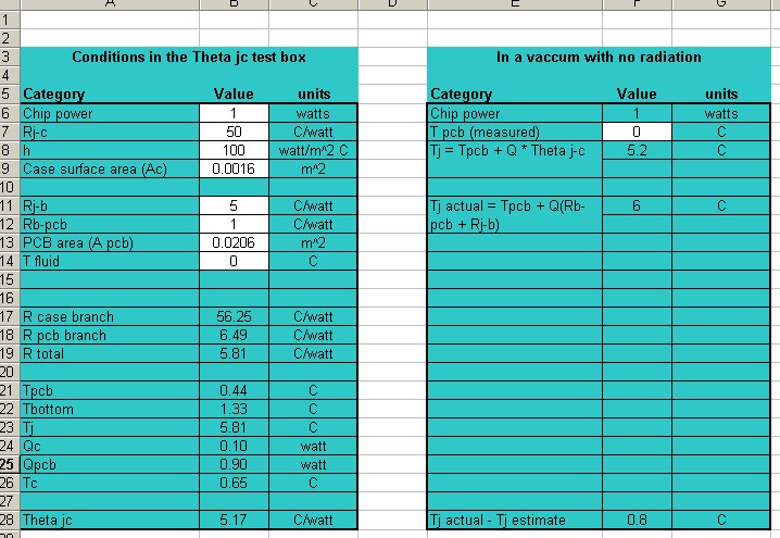
Figure 3. When the resistance from junction to the top is much higher than to the bottom, the error in junction temperature is lower, although still not conservative. Note that Rj-b is 5 C/W and Rj-c is 50 C/W. With this very large difference in heat path resistances, the error is fairly small.
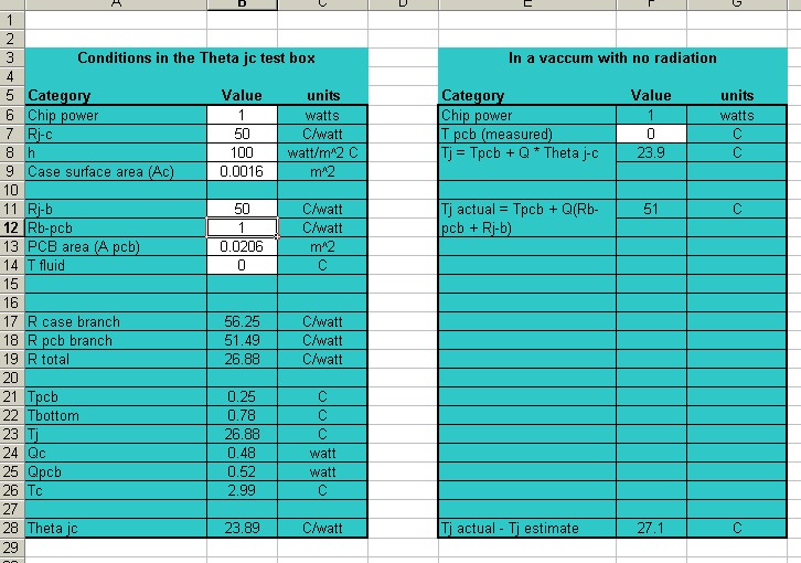
Figure 4. When Rj-c and Rj-b are about the same magnitude, the error is much larger, and is definitely NOT in the conservative direction. In both cases I have assumed that Rb-pcb is relatively small.
If you have any experience with electrical resistor networks, the explanation to this should be obvious (although it wasn’t to me.) What you have here is two resistors in parallel. The total resistance of the parallel resistors is always less than either one of them. If the two resistors are equal, than the total resistance is one half the value of one of them.
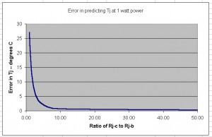
Figure 5. If resistance to the top of the package is relatively high, the error in Tj goes down. But it still isn't conservative.
Theta j-c is very similar to, although not exactly, the parallel combination of Rj-c and Rj-b . So Theta j-c MUST be smaller than either Rj-c or Rj-b, because they are in parallel with each other, at least during the JEDEC test. When you put your board in a vacuum, you force all the heat to flow through Rj-b, which is greater than Theta j-c by definition.
The sad conclusion is that your method can’t ever be conservative. Your estimate of Tj using Equation 1 will always be too low. The only time it might be safe to use is when the error is very small. This will happen only when Rj-c is much, much greater than Rj-b. The following graph shows how the error gets smaller as Rj-c gets larger and larger compared to Rj-b.
I don’t know what realistic values of Rj-c and Rj-b are for the types of component packages you might use. In fact, I don’t know any of those values off the top of my head. I suppose you could estimate them from details of the component package construction and material properties. But I don’t need to know any of that to say my point has been made. Your method for estimating junction temperature is not conservative.
But what if there is radiation?
Oh, right, I forgot that I had neglected radiation and would come back to it. Radiation is probably a significant heat path in any vacuum application, but it is difficult to say how much radiation will be lost from the top surface of a component without knowing the surroundings. After all, the net radiation depends on the emissivity, surface temperature, and view factor for any nearby surfaces.
If there is significant radiation, then some of the heat from the die will flow through Rj-c, and some through Rj-b, similar to a component in a convection environment. There may be some combinations of Rj-c, Rj-b, and radiation that would produce a conservative estimate of junction temperature using Equation 1. You could make a variation of my spreadsheet to include radiation losses and try some “what ifs” yourself, as a homework problem. But it should be obvious by now that there is no guarantee that it is conservative. Looks like you still need a better method of calculating Tj.
DOWNLOAD THE THETA J-C SPREADSHEET
—————————————————————————————————————
Dear Sir:
These spreadsheets you keep tossing into your articles are cool and all, but they don’t always fit the kind of problem I need to work on. And you don’t go into a lot of detail of how you put it together so I can follow along and make my own. How can I learn to analyze thermal problems with spreadsheets, like the pros?
All Boxed-in in Squaresville
Dear Boxed,
Spreadsheets were originally designed for financial and statistics folks. That’s why it seems like all they can do is add up columns of costs and turn them into colorful pie charts. Maybe the included tutorials don’t make a good point of it, but a spreadsheet can be a really nifty engineering tool, too. If you want to teach yourself, get a copy of Byron S. Gottfried’s book Spreadsheet Tools for Engineers.
—————————————————————————————————————
Isn’t Everything He Knows Wrong, Too?
The straight dope on Tony Kordyban
Tony Kordyban has been an engineer in the field of electronics cooling for different telecom and power supply companies (who can keep track when they change names so frequently?) for the last twenty years. Maybe that doesn’t make him an expert in heat transfer theory, but it has certainly gained him a lot of experience in the ways NOT to cool electronics. He does have some book-learnin’, with a BS in Mechanical Engineering from the University of Detroit (motto:Detroit— no place for wimps) and a Masters in Mechanical Engineering from Stanford (motto: shouldn’t Nobels count more than Rose Bowls?)
 In those twenty years Tony has come to the conclusion that a lot of the common practices of electronics cooling are full of baloney. He has run into so much nonsense in the field that he has found it easier to just assume “everything you know is wrong” (from the comedy album by Firesign Theatre), and to question everything against the basic principles of heat transfer theory.
Tony has been collecting case studies of the wrong way to cool electronics, using them to educate the cooling masses, applying humor as the sugar to help the medicine go down. These have been published recently by the ASME Press in a book called, “Hot Air Rises and Heat Sinks: Everything You Know About Cooling Electronics Is Wrong.” It is available direct from ASME Press at 1-800-843-2763 or at their web site at http://www.asme.org/pubs/asmepress, Order Number 800741.