Answers to those Doggone Thermal Design Questions
By Tony Kordyban
Copyright by Tony Kordyban 2003
Dear Tony,
Currently I use a finite element analysis (FEA) tool for thermal design of our electronic products. To design a heat sink, I only need to input average Heat Transfer Coefficient, h, for the convection boundary condition on heat sink flow areas, and then the whole thermal model is numerically solved. I don’t have a CFD tool available, so I use empirical formulas to hand calculate h. But I’m not sure I’m using the right equations to do that. Our product design heavily relies on the thermal simulation because of the lack of experimental tools.
For a pin fin heat sink I use the empirical equations for flow across tube banks from “Heat Transfer” by J.P. Holman, to take into account the effect of multiple rows of pins. Do you think this is good enough or you can recommend better literature for me to use?
For a plate fin heat sink, I use the equation in the same book for fully developed laminar flow in rectangular ducts. The Heat Transfer Coefficient “h” for pin fins is several times higher than plate fins. I believe pin fins should perform better because pins can generate turbulence in surrounding air. But I’ve been told by different people that pin fin sinks always looks better in simulation but in real life a plate sink is better (of course, if air flow direction is known). What do you think about this? If it’s true, the critical thing is, should I “downgrade” pin fin results or “upgrade” plate fin result in modeling?
Pinned to the Mat in Matteson
Dear Pinned,
You don’t have CFD, and you don’t have any experimental facilities. You are in trouble. I am glad that you found your way to J. P. Holman at least. Unfortunately, that text will probably not do you much good in this case either.
What correlation from the extensive heat transfer literature would be best from estimating convective coefficient for a pin fin heat sink? Maybe you will be surprised at the answer I give later. For now, to build up a little suspense, let’s discuss the correlations you already mentioned.
Which correlation gives a more realistic value of “h” for a pin fin sink: the one for flow across a bundle of tubes, or the one for laminar flow in a rectangular duct? They give very different values, so if one is right and the other wrong, it is important to know. If the tube bundle correlation is valid, then you should always use pin fins, because “h” is so much higher than for a plate fin sink of the same size and surface area.
When applying a correlation from literature, one very important thing to keep in mind is similarity. The researchers went to a lot of trouble to non-dimesionalize their equations so that you don’t have to have the same fluid, the same dimensions, or the same velocity that they used to derive the equation. Some people say that they write their equations using Nusselt and Reynolds numbers just to confuse the ordinary engineer and make themselves seem smarter than everybody else. Maybe that is true, but it does allow the correlation to be used for a much wider range of problems. But for the correlation to be valid, you must have similar geometry, and a similar flow pattern. You shouldn’t use the correlation for a flat plate to find “h” for a sphere, for example. And an equation for laminar flow isn’t good for a turbulent flow problem, of course.
 Flow through a pin fin sink at least superficially is similar to flow through bundles or banks of tubes. The bundles these correlations were developed for were the pipes carrying feedwater into coal-fired boilers. These tubes were very big, very long, and the temperature gradient was very large compared to pin fin sinks. One of the basic assumptions in tube bundle correlations is that the tubes are infinitely long in the direction perpendicular to the flow (or at least very, very long compared to the diameter and spacing of the tubes in the bundle.) With infinitely long tubes, the flow through them is 2-dimensional. The flow zig-zags around each tube, but there is no flow in the direction parallel to the tubes.
The pins in a pin fin sink are not very infinite. One end of the pins terminate in the base of the sink. At the other end of the pins, the flow is open to the atmosphere. Air is free to flow parallel to the pins and leak out the top of the heat sink. Nothing forces the flow to stay inside the field of pins if the flow restriction is too high. For that reason, I think there is not enough similarity in the flow pattern to use the correlation for bundles of tubes.
What about the correlation for flow in a duct? If the pin fins are in-line, the channels between the fins might act like ducts. Obviously this wouldn’t work if the pins were staggered so that the flow is not in a straight line. The pin fin sink seems to be more like duct flow than flow through bundles of infinitely long tubes. But there are still some problems with similarity, which you have probably noticed. The “walls” of the ducts, or flow channels, are not continuous, but are regularly broken by the gaps between the pins in the flow direction. So the boundary layer doesn’t build up along those “walls” the way it would in a smooth duct.
And even though we don’t need the duct to be infinite in any direction for its correlation to apply, we still have the problem of the open “top” of the heat sink. Flow is not confined to the duct, and can leak out. For those two reasons, the flow pattern through a pin fin sink is probably not similar to duct flow. Not similar enough to justify using laminar flow duct correlations.
 The same problem exists for the correlations for flat plates. The flow pattern is likely not similar enough. Once you have eliminated flow over cylinders, tube bundles, flat plates, and through ducts, you have exhausted the classical literature. I don’t think you are going to find any papers giving correlations for “flow through stubby cylinders with a closed wall on one side and open leakage path on the other, with flow bypass allowed”.
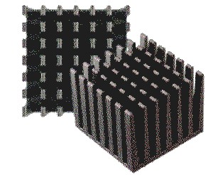
Let’s take a look at how much variation there is between the different correlations that you might try with a heat sink. I picked a pin fin sink from a vendor catalog, one that had an  equivalent plate fin version for comparison. (In reality, the pin fin sink is made by machining cross-cuts into the extruded plate fin sink.)
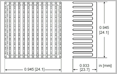
I have plotted the heat sink thermal resistance as a function of the approaching air velocity. For a change, I have not given the equations and the values of air properties that were used in the calculations. If you are interested, look in Chapter 5 of Holman. I know we were talking about “h”, but I have plotted thermal resistance R, which is 1/(h A). I did that because the vendor gave the thermal resistance curves for the heat sinks, not “h”. This brings up the question, “What is the surface area of a pin fin sink?” Should you count all the area of all the pins, or only the “effective” area, that which is in contact with the air flow? That all depends on how the correlation was derived. If you are using tube bundles, you should use all the pin surface area. For duct flow, probably only the duct “wall area”. Or maybe not. It is all debatable.
Anyway, notice the huge range of thermal resistance. The tube bundle prediction is very different from the results for flat plate or duct flow. And they are all way off from the published values for thermal resistance from the vendor. We can’t blame this on the vendor trying to exaggerate the performance of their products, because they give much higher thermal resistance values than the correlations predict.
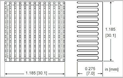 I made the same calculations for a different heat sink. It has the same number of pins, but they are much shorter, and the base is larger.
Note the correlations are still off, although the duct flow correlation comes closer for this design. The most interesting thing I notice is that the vendor thinks that pin fin and plate fin
sinks of the same geometry have very similar thermal resistances. The pin fin sink is slightly better in both cases. But at least in these graphs, there does not seem to be a very strong reason to use a pin fin in place of a plate fin sink, unless the flow direction is not known.
 The vendor data does not support the idea that “h” for pin fins is many times higher than the equivalent plate fins, as the tube bundle correlation suggests.
Here are some lessons learned, admittedly from a very small number of examples:
- don’t use the tube bundle correlations for pin fins
- if you have to use any correlation from textbooks, laminar duct flow seems to be the closest, although it can be too optimistic
- pin fin and plate fin sinks of similar geometry have pretty much the same thermal resistance
So what source do I recommend for finding “h” for a new heat sink design? The heat sink vendor. For off-the-shelf pin fin sinks, they should already have wind tunnel data. (I know, I know, I have criticized vendor data for heat sinks in the past. It has problems with accuracy, too, such as lumping in the radiation losses into the sink thermal resistance. But where else will you get any experimental data on pin fins?)
If you are designing a new pin fin sink from scratch, and want to estimate “h”, find an off-the-shelf sink with a similar geometry (pin size, pin spacing, flow length) and borrow its value of “h” published by the vendor. Be careful to find out if “h” was measured with “ducted flow” or with “bypass”. Ducted flow means the sink was surrounded by solid walls that force all the air to stay inside the pin field. Bypass means that flow was allowed to leak out of the heat sink. Use the value that matches the way you will use the heat sink in your application. And if you can’t find a similar pin fin sink, find a similar plate fin sink. “h” is almost the same.
Since you are using a single, generic value of “h” in your FEA tool, I hope you are not bothering to model every single pin fin in detail. Just ignore all the detailed geometry, inflate the value of “h” to incorporate the surface area of all the pins, and save some grid.
I am anticipating your next question: but we use the lowest-cost aluminum fab house to make our heat sinks. They don’t have wind tunnels or publish data on off-the-shelf sinks. What can we do?
You don’t have CFD, you don’t have experimental facilities, and you don’t want to pay extra for heat sinks that have published data sheets. How critical did you say the thermal design was to the success of your product?
—————————————————————————————————————
Dear Thermal Question Person,
What is a push-pull fan? I read about using fans in a push-pull arrangement, but the article didn’t have any pictures of it. All I can think of is something like a Japanese hand fan that flaps back and forth. On each swing it either “pushes” or “pulls” the air along. Is there a use for this in electronics? Is there a cooling fan that alternates between blowing and then sucking the air through a box, so the air flow switches directions every cycle?
Flapping in the Breeze
Dear Flap,
Maybe there is a use for the reversing fan that you have dreamed up, but that is not what the term “push-pull” means. In a push-pull arrangement, there is one fan (or more) on the inlet of a chassis, and a second fan (or multiple fans) on the exit of the chassis. The inlet fan “pushes”, and, at the same time, the exit fan “pulls”. It is a nice way of putting fans in series. By putting the fans on opposite ends of the chassis, they are far enough apart that they don’t interfere with each other.
 The benefit of putting fans in series is that you increase the pressure available, compared to a single fan. (Fans in parallel add their flow rates. Fans in series add their pressures.) Doubling the pressure does not usually double the flow rate through the chassis. The operating point depends on the interaction of the fan performance curve and the system resistance curve.
A disadvantage of the push-pull arrangement is that the fans are physically separated. That makes the power and control wiring more complicated, and means that there are now two replaceable fan units per chassis instead of just one. (Remember, fans usually fail before the electronics.
Another tip to keep in mind if you decide to use push-pull fans is to use matching fans at the inlet and outlet. If you use large, powerful fans at one end, and tiny, weak fans at the other, they won’t add together. The weak fans will end up being a drag on the powerful ones. It’s like adding a Chihuahua to your Husky dog sled team. The little guy won’t add anything and the big dogs will just drag him along.
Maybe the flapping fan you imagined would be useful for stirring the air around in a sealed box application. I am going to start looking at that in my spare time. I wonder how you would model that in a CFD tool?
—————————————————————————————————————
Isn’t Everything He Knows Wrong, Too?
The straight dope on Tony Kordyban
Tony Kordyban has been an engineer in the field of electronics cooling for different telecom and power supply companies (who can keep track when they change names so frequently?) for the last twenty years. Maybe that doesn’t make him an expert in heat transfer theory, but it has certainly gained him a lot of experience in the ways NOT to cool electronics. He does have some book-learnin’, with a BS in Mechanical Engineering from the University of Detroit (motto:Detroit— no place for wimps) and a Masters in Mechanical Engineering from Stanford (motto: shouldn’t Nobels count more than Rose Bowls?)
 In those twenty years Tony has come to the conclusion that a lot of the common practices of electronics cooling are full of baloney. He has run into so much nonsense in the field that he has found it easier to just assume “everything you know is wrong” (from the comedy album by Firesign Theatre), and to question everything against the basic principles of heat transfer theory.
Tony has been collecting case studies of the wrong way to cool electronics, using them to educate the cooling masses, applying humor as the sugar to help the medicine go down. These have been published recently by the ASME Press in a book called, “Hot Air Rises and Heat Sinks: Everything You Know About Cooling Electronics Is Wrong.” It is available direct from ASME Press at 1-800-843-2763 or at their web site at http://www.asme.org/pubs/asmepress, Order Number 800741.