Answers to those Doggone Thermal Design Questions
By Tony Kordyban
Copyright by Tony Kordyban 2002
Dear Tony,
Long time reader, first time writer. I am seeking design information to size a chimney for use in an a electronics packaging application. Can you point me to any existing work, or even better, provide me with the equations? CFD is not an option at this time.
Bert from Mary Poppins
Dear Bert,
If you mention the phrase “natural convection” at the cafeteria lunch table, somebody is bound to respond with, “ah, yes, the chimney effect.” I find it curious that everybody knows about “the chimney effect” except me. None of my college heat transfer courses mentioned such a thing. (There was a course in power plant design, and it did mention that you want to have very tall chimneys on your coal-fired boilers so that the pollution ends up in another legal jurisdiction, but that is a totally different “chimney effect”.)

Figure 1. A very, un-chimney-like electronic chassis. There is very little air flow through the horizontally oriented vents. The buoyancy of the hot air mostly generates small recirculating currents inside the box.
Heat transfer specialists have a special jargon for the “chimney effect”: gravity. In natural convection, a hot object heats up the surrounding air. The hot air is less dense than the surrounding cold air. Then, as everybody knows, “hot air rises.” Actually, it is the other way around. Cold air falls. Gravity pulls more on cold air, because it is denser. The heavier, colder air is pulled to the bottom of the pile of air, and that pushes the hot air upward out of the way. The “buoyancy effect” is really just gravity sorting out air, pulling the heaviest air down close to the earth and letting the lightest air pop up to the top of the stack.
So because of gravity, cold air moves downward and hot air moves upward. What does that have to do with a chimney? Let’s say you have an electronics chassis like the one in Figure 1. There are vents at opposite ends of the chassis, but no fan. The electronics inside generate heat, so soon there is a both hot and cold air inside the

Figure 2. When you line up the heat source and the vents with the direction that the air wants to flow anyhow, you get what is called "the chimney effect."
chassis. But because there is no height difference between the two vents, there is no tendency for the buoyant hot air, which want to move up, to leave the box at all. It stagnates against the inside of the roof of the chassis.
Figure 2 shows the same chassis turned 90 degrees, so that one vent is lower than the other. (Even a small angle would be enough to get the flow started.) Now the rising hot air can easily flow right out of the upper vent, and cooler ambient air can replace it by flowing into the lower vent. A natural flow is established through the box, and this increases the rate of heat transfer and lowers the temperature of the electronics. Natural convection works a lot better for vertically vented boxes such as in Figure 2 than for horizontal boxes such as in Figure 1. A vertical box with vertical flow looks more like a chimney, so I suppose that is where the phrase “chimney effect” comes from.
Gravity is the reason that the vertical direction works and horizontal doesn’t. For natural convection, the inlet and exit vents need to have vertical separation, and usually, the bigger the separation, the better.
But, Bert, you already knew all that. I just wanted to make sure that people didn’t think there was something magic about the shape of a chimney that made it generate air flow all by itself. The heat creates the density change, and gravity provides the force to make the air flow. The “chimney” is just an enclosure that doesn’t interfere with the direction the air wants to flow under the force of gravity. Now for those equations you’ve been waiting for.
I am taking the equations and explanation here directly from Gordon Ellison’s book Thermal Computations for Electronic Equipment. If you have a copy, you’d be better off reading it there in Chapter 6. But because it is out of print, I’m going to give you the equations right here.
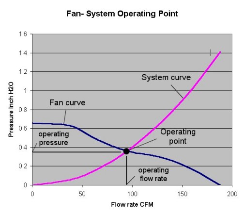
Here is the method for finding the flow rate through a chassis in natural convection. It is similar to finding the flow rate through a chassis with a fan. The fan is a driving force that produces different flow rates at different pressures. Against higher pressure, there is less flow. This characteristic of a fan can be shown as a performance curve. Likewise, a curve can be found for the flow resistance of the chassis. The higher the pressure applied, the greater the flow. The flow rate and pressure drop (the operating point) for the combination of the chassis and the fan is where the fan curve and the system resistance curves cross. That is where the flow resistance balances out the driving force of the fan.
I’m going to assume you know how to find the system resistance curve of your chassis. If not, search hard and get a copy of Ellison’s book. It’s all in there. But for natural convection, you don’t have a fan curve. What do you use for the driving force?
A fan curve usually (in the US) gives the driving force in terms of pressure (inches of water) as a function of volumetric flow rate (cubic feet per minute or CFM). Ellison gives a pair of equations that give the same kind of curve for natural convection. It is not an empirical relation, but is derived from first principles. I’m not going to duplicate his derivation. Please find the book in a library if you want to see how he derives this. It is not hard to follow.
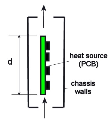
The following equations assume the geometry in this figure. The chassis is oriented vertically so that air flows straight through from bottom to top. The heat source (in our case, a circuit board) gives off heat uniformly so that the air temperature rises linearly as it passes over the board. Note that the vertical dimension, d, is the height over which the temperature increases, not the height of the chassis.
The increase in air temperature causes a change in air density, which generates a driving force for air flow. This force can be expressed as a pressure difference. The Ellison equations are:
|
where the terms are defined as: |
|
|
is the pressure difference in units of inches of water (in. H2O) |
|
|
d |
is the vertical length of the heat source, in inches |
|
is the temperature rise of the air over the length of the heat source, in degrees C. It is not the temperature rise of the heat source. This can also be thought of as the exit temperature – inlet temperature |
|
|
T0 |
the inlet air temperature, in °C |
|
G |
the volumetric air flow rate, in CFM (cubic feet per minute) |
|
Q |
is the heat flow rate of the heat source, in watts |
You don’t really need two equations. It’s just easier to write them out this way, plus you can see how the pressure is generated by the temperature rise. You can substitute the second equation into the first and get a formula for
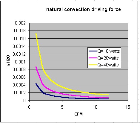
the pressure that only depends on four things: the vertical length of the heat source (d), the flow rate, the ambient temperature, and the power. You can use a simple spreadsheet to generate some pressure/flow rate curves for your intended design, that might look like this: (for a heat source 12 inches tall)
Notice that we got all this info about the driving force of natural convection without saying anything about the shape of the chimney, except for the vertical length of the heat source. Doesn’t the overall performance depend on things like the size of the inlet and exit vents? Or the cross sectional area of the chassis?
Yes. But those things determine the system resistance to flow. The geometry of your vents and your box and your PCB determine what the system resistance curve looks like. Then you plot it on this same graph, and where they cross is the approximate operating point.
Simple, eh? Maybe a little too simple. Most electronic boxes are not straight ducts, and most circuit boards are not uniform heat sources. So please remember that this is just a rough cut at estimating how a chassis will behave in natural convection. But it should be a pretty good cut, considering you didn’t have to invest in any CFD. You could probably do it even if you can’t afford a spreadsheet program. And if you don’t have a calculator, I have a used slide rule I can let you have, cheap.
—————————————————————————————————————
Isn’t Everything He Knows Wrong, Too?
The straight dope on Tony Kordyban
Tony Kordyban has been an engineer in the field of electronics cooling for different telecom and power supply companies (who can keep track when they change names so frequently?) for the last twenty years. Maybe that doesn’t make him an expert in heat transfer theory, but it has certainly gained him a lot of experience in the ways NOT to cool electronics. He does have some book-learnin’, with a BS in Mechanical Engineering from the University of Detroit (motto:Detroit— no place for wimps) and a Masters in Mechanical Engineering from Stanford (motto: shouldn’t Nobels count more than Rose Bowls?)
 In those twenty years Tony has come to the conclusion that a lot of the common practices of electronics cooling are full of baloney. He has run into so much nonsense in the field that he has found it easier to just assume “everything you know is wrong” (from the comedy album by Firesign Theatre), and to question everything against the basic principles of heat transfer theory.
Tony has been collecting case studies of the wrong way to cool electronics, using them to educate the cooling masses, applying humor as the sugar to help the medicine go down. These have been published recently by the ASME Press in a book called, “Hot Air Rises and Heat Sinks: Everything You Know About Cooling Electronics Is Wrong.” It is available direct from ASME Press at 1-800-843-2763 or at their web site at http://www.asme.org/pubs/asmepress, Order Number 800741.


