Answers to those Doggone Thermal Design Questions
By Tony Kordyban
Copyright by Tony Kordyban 2002
To the Thermal Explaining Guy,
What’s the deal with thermal interface materials? I’m referring to the whole collection of goops, greases, silicone pads and gap fillers intended to be stuck between a component and a heat sink. They are supposed to lower the thermal resistance between the component and the sink, compared to a “dry” joint (one that has no interface material.)
I guess they all work, by which I mean, they almost always are better than nothing at all. But how do you predict the thermal resistance of an interface material in a particular application? When I go by the thermal conductivity from the material data sheet, I predict a much lower temperature rise than I actually get. I could live with a little exaggeration from the material vendors, but it’s even worse than that. I used the same material on two different components, and for one the thermal resistance I measured was about three times higher than the other. What gives?
Missing Something in Cutters Gap
Dear Miss Ing,
You bring up a very touchy subject. I once saw two guys from rival thermal interface companies almost get into a fist fight at a technical conference. They were arguing about the appropriateness of a particular ASTM test method for measuring the conductivity of a Phase Change interface material. One had grabbed the other by the lapels and was about to head butt him, but they were suddenly distracted when both of their cell phones rang simultaneously.

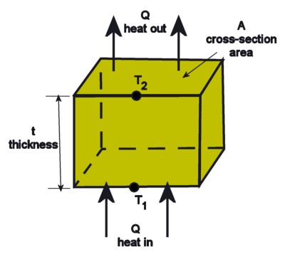
Thermal Resistance for one-dimensional conduction: T2 - T1 = Q t / ( k A ) and by definition R = (T2 - T1 ) / Q so R = t / (k A) where k is the conductivity of the solid block
The thermal resistance of interface materials is poorly understood, perhaps even by the scores of researchers working on it right now. I don’t think anybody (not even yours truly) has a good handle on it yet. At least not in a way that is useful to Electronics Cooling practitioners like you and me.
Before I get into why interface resistance is so tricky, let’s review what we mean by thermal resistance in the first place. Let’s say we have a simple, rigid solid, like a block of copper, with heat flowing through it from one face to another, like this:
So for a single, continuous, uniform solid you can calculate its thermal resistance from the thickness, the cross-sectional area, and the conductivity, which are all pretty easy to know. This is probably the method you used to estimate the resistance of your interface materials. It seems pretty simple. Why didn’t it work?
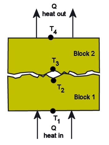
What happens if you stack two blocks of copper? You can easily find the resistance of Block 1 and Block 2 from the equation above. But there is also a “contact resistance” at the joint between Blocks 1 and 2. I have shown

The imperfect contact between two solids adds "contact resistance" to the total resistance of the assembly to the flow of heat.
the adjoining surfaces as being rough and irregular for a reason. The contact between them is definitely not perfect, and is full of tiny gaps, no matter how smooth and flat the surfaces appear to the naked eye. The contact resistance is not easy to estimate. It depends on things like the two materials in contact, their flatness, surface quality, and the pressure squeezing them together. It is the contact resistance you are trying to minimize by introducing an interface material.
So what is the situation with your component and heat sink?
Let’s say you put a squishy material between your component and heat sink. The resistance of the material layer itself is R = t/kA. But there are two other resistances to worry about — Rc1, the contact resistance between the material and the bottom of the heat sink, and Rc2, the contact resistance between the material and the top surface of the component package. Note that these two contact resistances are probably not equal, and have no reason to be.
Obviously, you are trying to get the total thermal resistance between the component and the air to be as low as possible. For that reason you would naturally choose the thinnest material that will still fill the gaps between the component and heat sink. The bulk resistance of the material increases with thickness. But if the thickness is very small, then the contact resistances (Rc1 and Rc2) dominate the total resistance of the joint. If that is true, then the conductivity of the material may not be very important at all.
The joint resistance may be mostly dependent on the contact pressure (the force squeezing the heat sink against the component), and/or the ability of the material to “wet” the surfaces. “Wetting” can be thought of as the material flowing into the microscopic cracks, crevices, nooks, crannies and pores in each surface, and displacing the air in those little  pockets. It doesn’t do any good to have a high conductivity material that traps a big air bubble in the center of the joint. The ability to wet a surface depends on what the two materials are, plus lots of other factors, like the presence of contaminants.
Then you have the problem that when you use a “squishy” interface material, and then squeeze it, it changes in thickness, surface area, and maybe in density, or in the distribution of filler particles in the matrix, so its “properties” may not be the same as when they were measured for the vendor’s data sheet.

Interface material can have a different thermal resistance when used with a plastic package than with a metal component package, just because the effective area of heat flow is different.
The total thermal resistance depends on so many factors that the only reliable way to know how a material will act in your application is to try it.
There is another reason why the performance of an interface would differ widely from one type of component package to another, even if contact resistance is negligible. The joint thermal resistance can depend on the conductivity of the component package. No, I’m not kidding.
Compare two 40 mm square Ball Grid Array (BGA) packages. Both have a 15 mm square die. One is overmolded in plastic ( k = 0.2 to 0.5 W/mK ) which does not spread heat well. The other is a flip-chip BGA that has a copper (k = 400 W/mK) heat spreader plate bonded to the upper surface of the die.
Let’s assume the interface material wets all the surfaces perfectly and contact resistance is negligible. Then the thermal resistance of the interface is R = t/(kA). The joint resistance is inversely proportional to A, the area through which heat flows (assuming the material thickness is the same). But in the case of the plastic BGA, heat does not spread sideways from the die because of its low conductivity. The effective area through the interface is only (15 mm)2, the area of the die. On the other hand, the copper heat spreader easily spreads the heat to the full (40 mm)2 area. The effective area is 7 times greater and the thermal resistance about 1/7 what you get with the plastic BGA.
So there doesn’t need to be any “exaggeration” by interface vendors for there to be huge variation in how their materials perform in your application. Get the vendors’ best advice for each application, and then proceed by trial and error. If that’s not fun enough for you, then invite a few representatives to visit on the same day, and have them duke it out in back by the loading dock.
—————————————————————————————————————
Isn’t Everything He Knows Wrong, Too?
The straight dope on Tony Kordyban
Tony Kordyban has been an engineer in the field of electronics cooling for different telecom and power supply companies (who can keep track when they change names so frequently?) for the last twenty years. Maybe that doesn’t make him an expert in heat transfer theory, but it has certainly gained him a lot of experience in the ways NOT to cool electronics. He does have some book-learnin’, with a BS in Mechanical Engineering from the University of Detroit (motto:Detroit— no place for wimps) and a Masters in Mechanical Engineering from Stanford (motto: shouldn’t Nobels count more than Rose Bowls?)
 In those twenty years Tony has come to the conclusion that a lot of the common practices of electronics cooling are full of baloney. He has run into so much nonsense in the field that he has found it easier to just assume “everything you know is wrong” (from the comedy album by Firesign Theatre), and to question everything against the basic principles of heat transfer theory.
Tony has been collecting case studies of the wrong way to cool electronics, using them to educate the cooling masses, applying humor as the sugar to help the medicine go down. These have been published recently by the ASME Press in a book called, “Hot Air Rises and Heat Sinks: Everything You Know About Cooling Electronics Is Wrong.” It is available direct from ASME Press at 1-800-843-2763 or at their web site at http://www.asme.org/pubs/asmepress, Order Number 800741.